Video Capture Adapter

@704E.ADF  VCA/A adapter (NTSC composite)
@70CE.ADF VCA/A PAL
vcpa.exe Video Capture Card/A API
videocap.com  Video Capture Adapter/A Option v1.10 
videocap.txt   Readme for videocap.com

Video Capture Adapter base Card
Video Capture Daughter Card
Primary I/O Cable Pinout (NTSC and PAL)


Video Capture Adapter Base Card
J1 72 Pin Socket 
U2 Xilinx XC2064-70 PC68C 
U25 Xilinx XC3020-50 PC68C 
U32  N82S181CA 
U35 Xilinx XC2018-70 PC84C
U40 TI -2FML TMS27PC256 
U42, U70 Xilinx XC2018-70 PC68C 
U46-U52 TI TMS4461-12SDL (x6)  TARAM
U53-U69 TI TMS4461-12SDL (x17)
0

TARAM - Translation Address Ram

Video Capture Daughter Card
J1 Holes for 26 Pin Header 
J2 72 Pin Header 
J3 20 Pin Port 
J4 S-VHS Port 
U5 Brooktree BT101HPJ 
U6 Xilinx XC2018-70 PC84C 
U13-U15 CA3306E
U22 Motorola MC1377FN 
U27 Motorola TDA3330 
U29 VTC (?) VA2706DJ 
U31 Philips DL-750 361579-6 
U32 Philips TDA2595 
Y1 3.5795 MHz Crystal
0

CA3306E 6-Bit, 15 MSPS, Flash A/D Converter
TDA2595 Horizontal combination
VA2706DJ Virtual Training Co Inc :: Dual General Purpose Op Amp - SR 42V/us,Io +/-50mA
MC1377FN Video Decoder-Encoder Circuit - RGB/NTS encoder
TDA3330  TV Color Processor

Video Capture Adapter/A
o   Enables user to capture high quality, photo-like images 
o   Full frame capture from motion video in 1/30 seconds 
o   Images can be manipulated and used in high quality presentations created with the AVC 
o   Uses RGB, NTSC (Composite Video) and Y/C (Super VHS) 
o   Captures 65,536 colors with a resolution of 640 X 480 X 16 bits 
o   Allows viewing live video during capture; the card is not required for general image presentation purposes 
o   614Kb dual-ported video RAM buffer 
o   Image display modes live, memory, overlay, transparent, pixel 

   The Video Capture Adapter/A provides the capability to capture, display and digitize high quality video images for use in presentations and applications with the Personal System/2 family models.  The adapter supports image capture with the PS/2 Models 50, 55 SX, 60, 70 and 80 and is intended for use with the
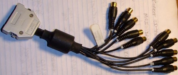
 AVC licensed program. 
       The adapter accepts video input signals through a multi-pin connection on the adapter.  The on-board processor converts the analog signal to a digital format that can be manipulated, compressed and stored by software for later use.  Sophisticated detailed image processing techniques employed in the AVC Image Editor Components enable the user to alter the characteristics of the digitized image as outlined in Programming Announcement 289-333.  The video adapter also contains output connectors, for attachment to a monitor, which allow the user to view live or captured images during the capturing process.  The adapter display capability is not required to run presentations containing captured images.  The standard PS/2 hardware alone enables the complete display of images for authoring and presentation purposes. 
       The video adapter end-bracket contains a 20-pin connector. The associated cable, included with the adapter, supports input/output jacks for connection to RGB (Red-Green-Blue), NTSC (National Television Standard Code, also known as Composite Video) and Y/C (Luminance/Chrominance) devices.  The Y/C capability allows the user to capture a significantly higher quality image than those available from NTSC.  Y/C devices, such as Super VHS video cameras and VCRs, are now emerging in the video marketplace. 

2. A Primary I/O Cable which has ten separate cables which end in RCA sockets, with a 20-pin connector on the other end. (For the VCA/A PAL adapter this is a Primary I/O cable with twelve separate cables which end in RCA sockets, with a 37-pin connector on the other end.)

     3. A S-Video Output Cable which is also used by the diagnostic program for a Y/C Wrap Cable. This cable has an S-Connector at one end and two RCA plugs at the other end. The BLACK RCA plug is the LUMA (Y) cable and the RED is the CHROMA (C) cable. (This cable is not included with the VCA/A PAL adapter. The VCA/A PAL adapter has two extra cables on the Primary I/O cable which serve as LUMA and CHROMA output connections.)

     4. Three 75 Ohm Terminators.

     5. A short cable with RCA plugs at both ends which is used by the diagnostic program in Wrap Tests for RGB and Composite Video. (There are two of these cables supplied with the VCA/A PAL adapter.)

     6. The diskette which has this README.DOC file, the diagnostic program and related modules, and two Adapter Definition Files (ADF). @704E.ADF is used during the CONFIGURATION step in the installation of the VCA/A adapter (NTSC composite). @70CE.ADF is used during the CONFIGURATION step in the installation of the VCA/A PAL adapter (PAL composite).

Primary I/O Cable Pinout

VCA/A NTSC and PAL

(NTSC composite): Leads numbered 1-10
Short leads 1-5
1 = Comp Sync Out
2 = Blue RGB Out
3 = Green RGB Out
4 = Red RGB Out
5 = Comp Video Out

Long leads 6-10
6 = Input Composite Sync
7 = Blue RGB Input
8 = Green RGB - Luma (Y) Y/C In
9 = Red RGB - Chroma (C) Y/C In
10 = Comp Video (NTSC) In

(PAL composite)
OS = Comp Sync Out
OB = Blue RGB Out
OG = Green RGB Out
OR = Red RGB Out
OV = Comp Video Out
IS =  Comp Sync In

IB = Blue RGB In
IG = Green RGB - Luma (Y) Y/C In
IR = Red RGB - Chroma (C) Y/C In
IV = Comp Video In
OC = Chroma (C) Y/C Out
OY = Luma (L) Y/C Output

  If you don't have an RGB monitor with 75 ohm termination, place RCA Term plugs on 2, 3, and 4. If RGB outputs are not terminated, the Y/C and Comp Video outputs will distort image brightness.  If you don't have an RGB monitor with 75 ohm termination, place RCA Term plugs on OR, OG, and OB. If RGB outputs are not terminated, the Y/C and Comp Video outputs will distort image brightness.

AdapterId 0704Eh "Video Capture Adapter/A" 

Video Storage Address Select
  System memory addresses dedicated to this adapter. D4000 to DBFFF or D8000 to DFFFF is recommended. At least 2 16k blocks are recommended for card memory to card memory operations.  If another choice must be made, try to use a selection with the most pages. The protect mode selection may be used if your operating system supports 'protect mode' such as OS/2. DOS does not support 'protect mode'."
   <"C0000-C3FFF">, D0000-DFFFF, D4000-DBFFF, D8000-DFFFF, D0000-D3FFF / D8000-DBFFF, D0000-D3FFF / DC000-DFFFF, D4000-D7FFF / DC000-DFFFF, D0000-D3FFF / CC000-CFFFF, D0000-D3FFF / C0000-C3FFF, D4000-D7FFF / C0000-C3FFF, D4000-D7FFF / CC000-CFFFF, D8000-DBFFF / C0000-C3FFF, D8000-DBFFF / CC000-CFFFF, CC000-CFFFF, D8000-DBFFF, F60000-FFFFFF / CC000-CFFFF
NOTE: Green addresses are two 16k windows

I/O Address Select
I/O port addresses dedicated to this adapter. 5D00-5D0F is recommended
  <"5D00-5D0F">, 5D10-5D1F, 7F00-7F0F, 7F10-7F1F, DD00-DD0F, DD10-DD1F, FF00-FF0F, FF10-FF1F

Interrupt Channel Select
IRQ used to signal an event. Interrupt 3 is recommended
<"Interrupt 3 ">, 5, 7, 9, 10, 11, 12, 15

9595 Main Page